
Current Capacity Based on Differences in Voltage and Load
These are conceptual reference values for microswitches, toggle switches, relays (1–10 A), and similar components.
Reference values based on a current capacity of 100% at 125 V AC. Reference values based on a current capacity of 100% for resistive loads.
| Voltage | Current |
|---|---|
| AC 125V | 100% |
| AC 250V | 70% (Micro SW 60) |
| DC 24V | 50% |
| DC 125V | 5% |
| DC 24V | [ Min. 50mA ] |
| Load | Current |
|---|---|
| Resistive load (COS φ = 1) |
100% |
| Inductive load (COS φ = 0.4) |
50% (Micro SW 60) |
| Motor Lamp | 15% (Micro SW 10) |
Load inrush current
These are conceptual reference values based on a resistive load.
| Load | Inrush current |
|---|---|
| Incandescent lamp | 10 to 15 times 0.3 to 0.4sec |
| Mercury vapor lamp | 3 to 4 times 3 to 5 minutes |
| Fluorescent light | 3 to 4 times 2 to 7sec |
| Motor | 5 to 10 times 0.2 to 5sec |
| Solenoid | 10 to 20 times Approx. 0.1 sec |
| Solenoid relay | 3 to 10 times 0.02 to 0.04sec |
Electrical Ratings for Gold Crossbar Contact Item
Inductive load
| Load | AC rating | DC rating |
|---|---|---|
| Resistive load | AC 125V 0.5A AC 50V 1A |
DC 40V 0.5A DC 24V 1A [ Min. DC 5V 1mA ] |
| Inductive load | AC 125V 0.2A AC 24V 1A |
DC 40V 0.2A DC 10V 1A |
When the circuit resistance specification after the end of life cycles is the same as the initial specification
Compatible Models
Thermostat time constant (thermal response speed)
The thermal response performance of a thermostat can be compared and evaluated using its time constant.
-
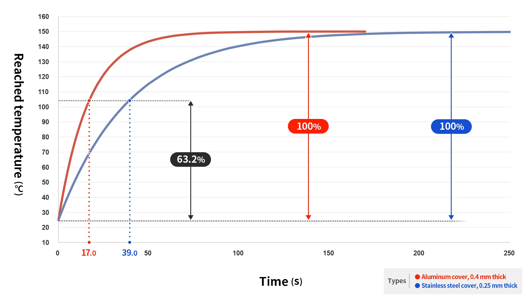
When a sample is heated from room temperature to a certain temperature, there is a time delay before the target temperature is reached.
The time it takes for the temperature difference between room temperature and the target temperature to reach 63.2% of that difference is the time constant (thermal response rate). -
-
How to Calculate the Time Constant Based on the Thermostat's Operating Time
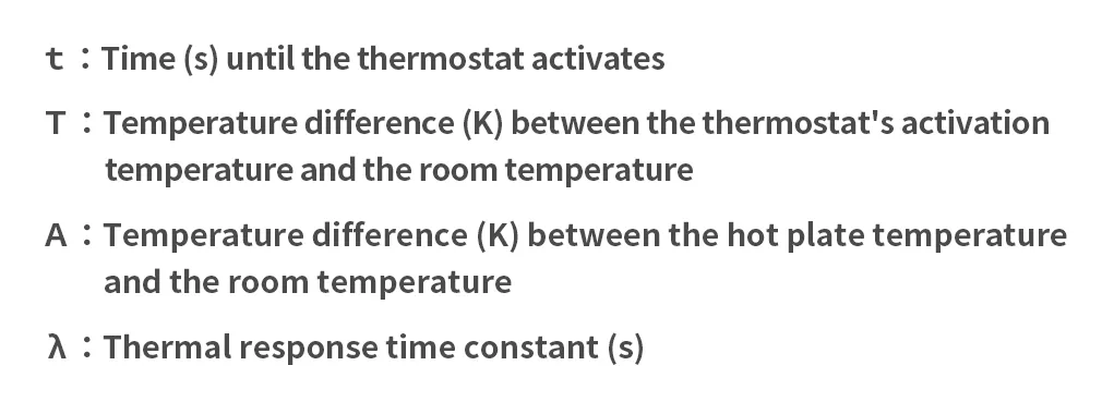
Place the thermostat on the hot plate and measure the time it takes to begin operating under constant pressure.
After the measurement, calculate the thermal response time constant using the formula below.
-
How to Measure Time Constants from a Test Implementation Chart (Temperature of a Bimetallic Disc)
Thermal response test on a heating plate when the thermostat cover material was changed from 0.4 mm aluminum to 0.25 mm stainless steel
Conditions: Aluminum heat plate temperature 150°C; no thermal grease used between the heat plate and the cover(This varies depending on the pressure, the shape and contact area of the cover, the material and shape of the bimetal, and whether grease is used.)Comparison of Response Characteristics Based on Cover Material on a Hot Plate: Temperature Tracking Characteristics Graph
Click the image to view a larger version
-